Verdict: heated area times 50 W per sq ft, then a panel check before anything is ordered
An Overland Park snow-melt system is sized at 50 watts per square foot of heated area at 240 V, elements spaced 3 inches apart and buried 1.5 to 3.0 inches below the finished surface, over a 10-inch compacted aggregate base. Those five numbers set the melt rate, the energy bill, the element cost and whether the load fits the service already in the house. Sizing on total driveway area instead of heated area is the single most expensive mistake in this trade.
Step 1: power density
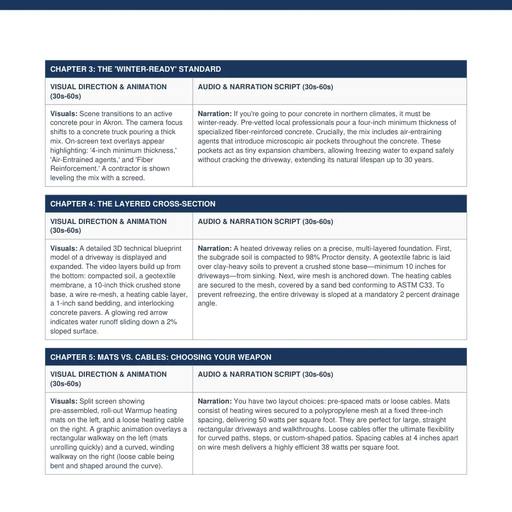
Power density is design output per square foot. At the standard 3-inch cable spacing, output is 50 W/sq ft, which melts 1 to 3 inches of snow per hour. Loose cable laid at a wider 4-inch spacing delivers 38 W/sq ft - less cable, lower load, slower recovery in a heavy storm. Mats remove the decision because the cable is factory-fixed to polypropylene mesh at 3 inches.
| Heated area | At 3 in. spacing (50 W/sq ft) | At 4 in. spacing (38 W/sq ft) | Amps at 240 V | Continuous rating (x1.25) |
|---|---|---|---|---|
| 80 sq ft (tire tracks) | 4.0 kW | 3.0 kW | 16.7 A | 20.8 A |
| 200 sq ft (walkway + approach) | 10.0 kW | 7.6 kW | 41.7 A | 52.1 A |
| 400 sq ft (20 x 20 full) | 20.0 kW | 15.2 kW | 83.3 A | 104.2 A |
| 600 sq ft (30 x 20 full) | 30.0 kW | 22.8 kW | 125.0 A | 156.3 A |
Treat the 4-inch column as a lever rather than a discount. On a 400 sq ft slab it cuts the load from 20 kW to 15.2 kW, which can be the difference between an installable system and one that needs a service upgrade -
Mats or loose cable is the same lever in a different place. A factory-fixed WSMM mat holds its 3-inch pitch through the pour and takes the spacing decision away from the crew; loose WSM cable is tied on site, so it can be laid at a wider 4-inch pitch for 38 W/sq ft or packed into partial coverage, at the cost of field labour and a spacing error no inspector will catch once the concrete is down. On a 400 sq ft slab that single choice is the whole difference between a 20 kW system and a 15.2 kW one - about a quarter less load, paid for with slower melt in the heaviest storms.
Step 2: the layered build-up, top to bottom
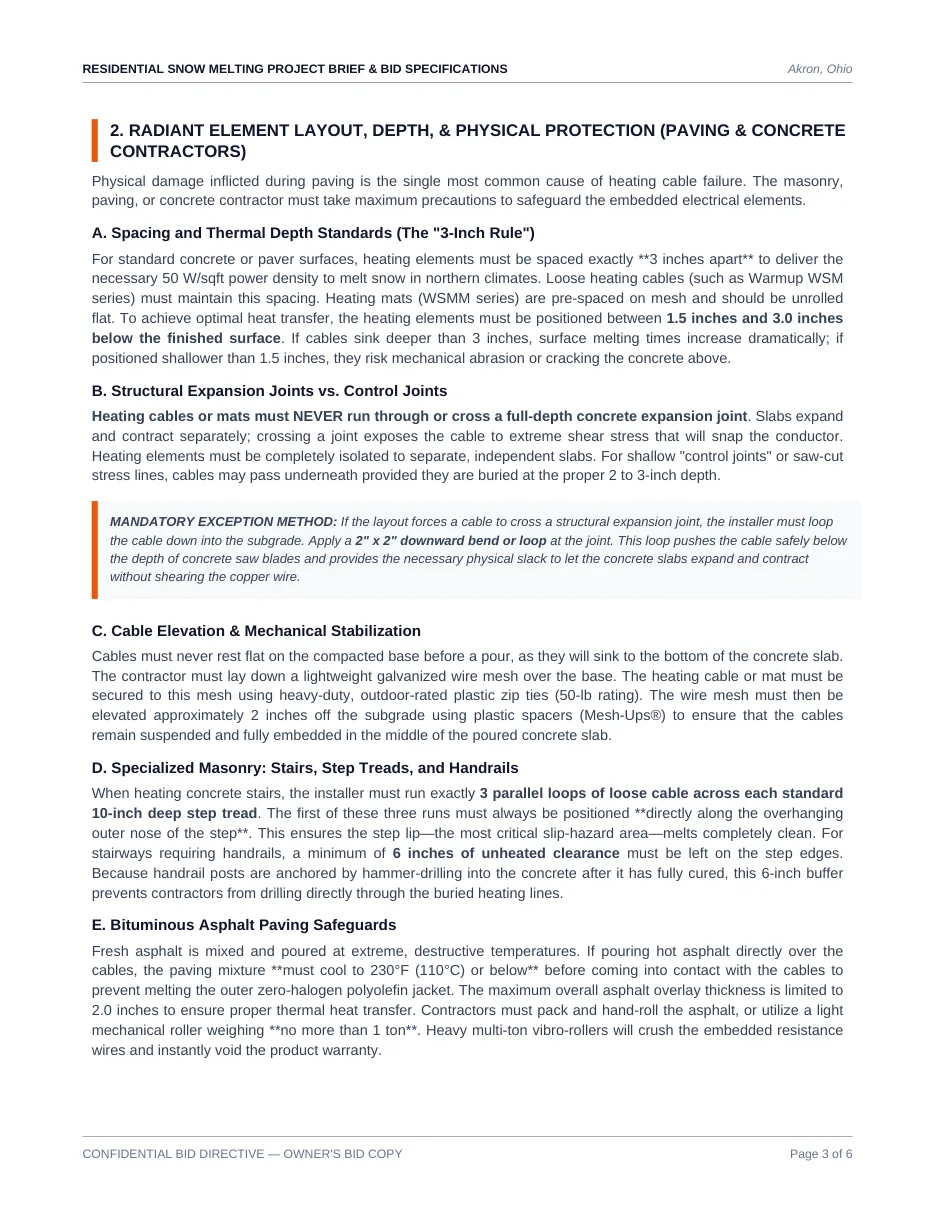
Element depth is a thermal budget. Deeper than 3 inches and surface melting times rise dramatically, because all the concrete between the cable and the weather has to be warmed first. Shallower than 1.5 inches and the cable risks abrasion during finishing and cracking the concrete directly above. Cables never sit flat on the base: they are tied to galvanised wire mesh that is itself held about 2 inches off the subgrade on plastic spacers, so the cable ends up suspended in the middle of the pour.
| Layer | Specification | Failure it prevents |
|---|---|---|
| Pavement | Concrete 4 in. minimum, fiber-reinforced, 6% air-entrained | Ice-pressure cracking and surface spalling |
| Element zone | Cables or mats 1.5 to 3.0 in. below the finished surface at 3 in. spacing | Slow melting, cold stripes, trowel damage |
| Mesh | Galvanised welded wire mesh, cable tied with 50 lb outdoor-rated zip ties | Cable sinking to the bottom of the slab |
| Elevation | Mesh raised about 2 in. off the base on plastic spacers | Cable stranded in the low-heat zone at the slab base |
| Aggregate base | 10 in. minimum for driveways, 6 in. for walkways; ASTM D 2490 gradation, No. 200 fines 0-8% | Frost heave and perched water beneath the slab |
| Separation and subgrade | Geotextile over compacted clay or silt; subgrade at 98% standard Proctor density (ASTM D 698) | Base stone pumping down into wet, plastic clay |
The geotextile line is not optional decoration in a clay subgrade. Expansive and weak clay soils are the reason the material spec adds a 15% base-thickness multiplier and makes a separation membrane mandatory - without it, angular base stone migrates downward over successive freeze-thaw cycles and the slab ends up supported unevenly. Geotextile costs almost nothing at pour time and cannot be retrofitted.
Step 3: control strategy decides the energy bill
A heated driveway does not run all winter. The specification calls for a forecast-based Wi-Fi controller with an aerial-mount snow switch and an in-slab temperature limit sensor. The controller reads local forecast data and pre-heats the slab hours before a storm, which makes it twice as effective at preventing accumulation; automatic moisture and temperature sensing cuts energy waste by up to 70% against a manual timer running on a fixed schedule.
| Control strategy | How it decides to run | Energy consequence |
|---|---|---|
| Manual timer | Fixed schedule, independent of weather | Heats dry pavement on mild days; the baseline the 70% figure is measured against |
| Slab sensor thermostat | Reacts once the slab nears freezing with moisture present | Reactive - the slab must cool first, so snow can accumulate before heat starts |
| Forecast-based Wi-Fi + aerial snow switch | Reads forecast data and pre-heats hours ahead of the storm | Up to 70% less wasted energy; pre-heating is twice as effective at preventing accumulation |
| Zoned sequencing | Cycles separate heating areas so peak draw never arrives at once | The workaround when continuous load exceeds 40% of the panel rating |
Placement decides whether that saving is real. The aerial snow sensor is post-mounted above the roofline with an unobstructed 360-degree sky view, clear of overhangs, trees and hot vents; a unit tucked under a soffit reads the wrong weather and defeats the forecast logic. The in-slab sensor sits flush with the pavement so the controller can end the cycle once the surface is dry
Check the panel while you are still sizing
A snow-melt system is only installable if the service can carry it, and that check belongs in the sizing step rather than the electrical quote. The governing rules are 40 amps of continuous load per branch circuit and no more than 40% of the main panel rating for the heating load alone. A 200 sq ft walkway at 10 kW draws 41.7 running amps and needs two 30-amp circuits, which fits a 200-amp service. A 400 sq ft full-coverage slab at 20 kW draws 83.3 running amps and 104.2 amps continuous, which does not. Before ordering elements, divide the continuous rating by 40 for the minimum breaker count, then check that total against 40% of the panel. Where it fails, the honest options are fewer heated square feet, a tire-track layout or a separate sub-panel - never a larger breaker on the same wire.
Storm duration changes nothing about the panel and everything about the bill. Demand is fixed at 50 W/sq ft whenever the system runs; what varies is how long a cycle lasts. A three-hour storm plus the mandatory three-hour after-run is six hours of draw, which is $19.20 on a 400 sq ft slab at 16¢/kWh; a twelve-hour event runs fifteen hours and costs $48.00. Forecast control is the mechanism that keeps a two-inch snowfall from billing the same as a blizzard, because the controller decides from the forecast when to pre-heat and when to stay off.
How to size it in the quote
Step 4: drain the meltwater
A snow-melt system converts solid snow to liquid water; it does not evaporate it. The specification makes a minimum finished surface slope of 2% - a quarter inch of drop per linear foot - mandatory, with runoff directed away from foundations and pedestrian zones and never discharged onto adjacent unheated pavement, where it will pool and refreeze into an ice sheet. On a 20-foot run that is 4.8 inches of fall. Anything under 1.5% is a standing-water design, and pooled water with road salt will scale a slab faster than any other mechanism short of a bad mix.
How to size it in the quote
- Choose coverage first - full slab or two 2-foot tyre tracks - because it sets heated area, element cost and energy cost together.
- Multiply heated area by 50 W/sq ft; divide by 240 V for running amps; multiply by 1.25 for the continuous rating.
- Confirm the continuous rating fits under 40 A per branch circuit and under 40% of the main panel rating.
- Require 3 in. spacing at 1.5 to 3.0 in. depth, suspended on mesh raised about 2 in. off the base.
- Require the 10 in. compacted base, geotextile over clay, and a 2% finished slope in the same contract.
- Specify forecast control, an above-roofline aerial sensor, an in-slab limit sensor, and sensor wiring in its own conduit.
Sources
The 50 W/sq ft design density, 240 V supply, 3-inch element spacing, 1.5 to 3.0 inch depth window, 10-inch driveway and 6-inch walkway base minimums, 98% standard Proctor compaction under ASTM D 698, geotextile over clay or silt, ASTM D 2490 gradation with its 0-8% fines limit, the forecast-based controller with aerial snow switch and in-slab limit sensor, and the mandatory 2% surface drainage slope are from the Residential Snow Melting Project Brief & Bid Specifications (v2.0, August 2026) at /media/concrete-driveways/pdfs/heated-driveway-contractor-brief.pdf. The 38 W/sq ft output at 4-inch loose-cable spacing, the 1-to-3-inch hourly melt rate, the 70% energy-waste reduction versus manual timers and the statement that forecast pre-heating doubles effectiveness are from the Anatomy of a Heated Driveway production script at /media/concrete-driveways/slides/. The 15% base-thickness multiplier and mandatory geotextile for weak or expansive clay soil are the clay-soil branch of the Concrete Paving & Driveway Calculator Development Prompts behind this site's calculators. All amp, kW and continuous-rating values are computed here from watts and 240 V with the 1.25 continuous-load factor. The reference brief was authored for a severe freeze-thaw Ohio siting profile with 47 in. average seasonal snowfall; its electrical and thermal constants are climate-independent, but base depth should be confirmed against your own soil conditions and current local requirements.