Verdict: 400 sq ft of full coverage will not fit a 200-amp service
A full-coverage system on a 20 x 20 ft driveway draws 20 kW. At 240 V that is 83.3 running amps and 104.2 amps of continuous-load rating. On a 200-amp service the safe allowance for a single continuous heating load is 40% of the panel - 80 amps - so that layout fails the check before any cable is laid. The same driveway as two 2-foot tire tracks draws 4 kW, 16.7 running amps and 20.8 continuous, fits a single 30-amp GFEP breaker, and clears the 40% rule with room to spare. Coverage choice, not equipment brand, decides whether the project needs a service upgrade or a zoned controller.
Continuous load is the whole game
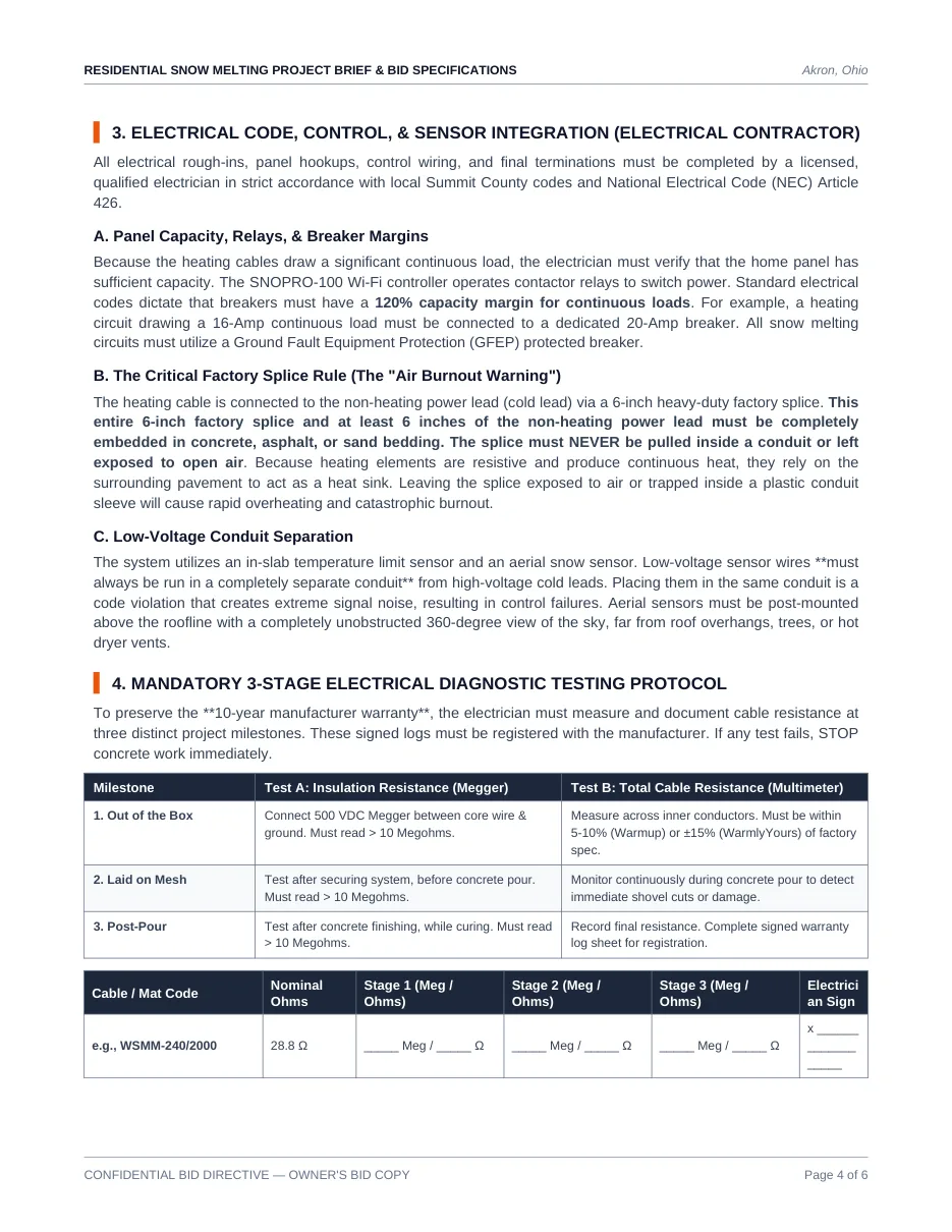
Heating cable is not a motor that cycles; it runs for hours. Under NEC Article 426, fixed outdoor de-icing and snow-melting equipment is treated as a continuous load, and the specification states the margin as 120% with a worked example: a circuit drawing 16 amps continuous connects to a dedicated 20-amp breaker. In practice the branch circuit is sized at 1.25 times running amperage and then rounded up to the next standard double-pole rating.
| Heated area | Draw at 50 W/sq ft | Running amps at 240 V | Continuous rating (x1.25) | 40 A branch circuits | Breaker per circuit |
|---|---|---|---|---|---|
| 80 sq ft (tire tracks) | 4 kW | 16.7 A | 20.8 A | 1 | 30 A |
| 100 sq ft | 5 kW | 20.8 A | 26.0 A | 1 | 30 A |
| 200 sq ft (walkway + approach) | 10 kW | 41.7 A | 52.1 A | 2 | 30 A |
| 400 sq ft (20 x 20 full) | 20 kW | 83.3 A | 104.2 A | 3 | 40 A |
| 600 sq ft (30 x 20 full) | 30 kW | 125.0 A | 156.3 A | 4 | 40 A |
Residential branch circuits for heating cable are limited to 40 amps of continuous load each, so the number of double-pole GFEP breakers is the continuous rating divided by 40, rounded up. That is why a 400 sq ft full-coverage installation arrives with three 40-amp breakers rather than one large one, and why the load must be split across zones rather than delivered on a single feed.
The 40%-of-panel rule against real services
A residential service should never allocate more than 40% of its main panel rating to a single continuous heating load: 40 amps on a 100-amp panel, 80 amps on a 200-amp panel, 160 amps on a 400-amp panel.
| Layout | Continuous load | 100 A panel (40 A) | 200 A panel (80 A) | 400 A panel (160 A) |
|---|---|---|---|---|
| 80 sq ft tire tracks | 20.8 A | Fits | Fits | Fits |
| 100 sq ft | 26.0 A | Fits | Fits | Fits |
| 200 sq ft | 52.1 A | Fails | Fits | Fits |
| 400 sq ft full | 104.2 A | Fails | Fails | Fits |
| 600 sq ft full | 156.3 A | Fails | Fails | Fits with 3.7 A to spare |
When the load exceeds the allowance, the specification names three competent responses: reduce heated square footage, switch to an optimised tire-track layout, or install sequentially zoned control panels that cycle heating areas so peak draw never arrives at once. A fourth - upgrading the service - is a real project with real cost, and
Working backwards from the panel rating
The constraint reads from the other end too: given the service already in the house, how much full coverage will it carry? Invert the arithmetic - panel rating x 40%, divided by the 1.25 continuous factor, converted to watts at 240 V, divided by 50 W/sq ft. That puts a 100-amp panel at about 154 sq ft of full coverage, a 200-amp panel at about 307 sq ft and a 400-amp panel at about 614 sq ft. A 20 x 20 ft driveway is 400 sq ft, so it needs more than a 200-amp service unless the layout drops to tire tracks.
| Main panel rating | Heating allowance (40%) | Running amps with 1.25 headroom | Available output | Maximum full-coverage heated area |
|---|---|---|---|---|
| 100 A | 40.0 A | 32.0 A | 7.7 kW | 154 sq ft |
| 200 A | 80.0 A | 64.0 A | 15.4 kW | 307 sq ft |
| 400 A | 160.0 A | 128.0 A | 30.7 kW | 614 sq ft |
The electrical work behind that table is a quotable line rather than a hidden one: a licensed electrician integrating the panel, the GFEP breakers and the conduit runs lands between $1,000 and $2,500 in the reference ledger, and that figure assumes the panel already has the spare capacity. Where the panel does not, the service upgrade is a separate project and belongs on its own line of the bid so it cannot be absorbed into a change order.
GFEP, not GFCI, and the 30 mA threshold
All snow-melting circuits must use a Ground Fault Equipment Protection breaker, specified at a 30 mA trip threshold. That level protects the equipment - the buried cable and its jacket - rather than people, which is why it is not interchangeable with the 5 mA GFCI used on receptacles. A heating cable buried in wet concrete is precisely the failure case this device exists for, so the specification makes it mandatory rather than optional. The supply path runs from the main service panel to a touchscreen or Wi-Fi controller with contactor relays, then to the double-pole GFEP breakers, then to a weatherproof junction box, then to the embedded cables.
The splice that burns out in minutes
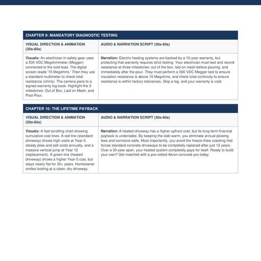
Heating cable terminates in a 6-inch factory hot-to-cold splice connecting the resistive element to the non-heating power lead. That whole 6-inch splice, plus at least 6 inches of cold lead, must be fully embedded in concrete, asphalt or sand bedding. Resistive elements produce heat continuously and rely on the surrounding pavement as a heat sink; pulled into a conduit or left in open air, the splice overheats and burns out - inside a conduit, in minutes. Separately, low-voltage sensor wiring must run in its own conduit: sharing one with the high-voltage cold leads is a code violation that injects signal noise and causes control failures.
Testing, and the warranty you lose by skipping it
The 10-year manufacturer warranty is conditional on documented testing at three milestones. Test A is insulation resistance measured with a 500 VDC megohmmeter between the core conductor and the ground braid, and must read above 10 megohms. Test B is total cable resistance measured with a digital multimeter across the inner conductors, and must fall within 5 to 10% of nominal for Warmup systems or within plus or minus 15% for WarmlyYours. Both tests run out of the box, once the cable is laid on mesh but before the pour, and again post-pour while the concrete cures. The post-pour test matters most: a shovel nick during the pour is invisible, and the signed log is the only evidence the circuit was intact before the slab went down.
| Milestone | Test A: insulation resistance | Test B: cable resistance | Purpose |
|---|---|---|---|
| Out of the box | 500 VDC Megger, core to ground braid, above 10 megohms | Within 5-10% (Warmup) or plus/minus 15% (WarmlyYours) of factory spec | Reject damaged stock before it is buried |
| Laid on mesh, pre-pour | Above 10 megohms once the system is secured | Monitor during the pour to catch shovel cuts immediately | Catch installation damage while it is still fixable |
| Post-pour, curing | Above 10 megohms after finishing | Record final resistance and complete the signed warranty log | Registers the 10-year warranty |
Electrical checklist for the quote
- State the heated area, calculated draw in kW, running amps and the 1.25 continuous rating in the quote.
- Show the breaker count and sizes: continuous rating divided by 40 A per branch circuit, rounded up, in standard double-pole sizes.
- Show the 40%-of-panel arithmetic against the actual main service rating, and quote any service upgrade separately.
- Require GFEP double-pole breakers at 30 mA on every snow-melt circuit.
- Require the 6-inch factory splice and at least 6 inches of cold lead fully embedded, never inside a conduit.
- Require low-voltage sensor wiring in a separate conduit and the aerial sensor mounted above the roofline with a 360-degree sky view.
- Require signed three-stage test logs with ohm values recorded against nominal.
Sources
NEC Article 426 as the governing code, the 120% breaker margin with the worked 16-amp-to-20-amp example, the mandatory GFEP breaker, the 6-inch factory hot-to-cold splice embedment rule with at least 6 inches of cold lead, the prohibition on pulling the splice into a conduit, the separate-conduit rule for low-voltage sensor wiring, the aerial sensor's 360-degree unobstructed sky view, and the three-stage testing protocol with the greater-than-10-megohm Megger threshold and the 5-10% / plus-minus-15% resistance tolerances are from the Residential Snow Melting Project Brief & Bid Specifications (v2.0, August 2026) at /media/concrete-driveways/pdfs/heated-driveway-contractor-brief.pdf. The statement that a splice inside a conduit overheats and burns out in minutes, and the 10-year warranty condition, are from the Anatomy of a Heated Driveway production script at /media/concrete-driveways/slides/. The 40-amp continuous limit per residential branch circuit, the 40%-of-panel allocation rule, the 30 mA GFEP trip level, the 125% continuous-load factor and the standard breaker sizes are the constants in the Concrete Paving & Driveway Calculator Development Prompts behind this site's sub-panel and GFEP sizer and the live heated-driveway calculator. All amp, kW, breaker-count and panel-fit figures are computed here from watts divided by 240 V and multiplied by 1.25, with no other assumptions. The $1,000-to-$2,500 electrician figure for panel integration, GFEP breakers and conduit is from the concrete notebook's content blueprints. Panel ratings and the branch-circuit limit are code-derived constants rather than local ones - confirm the actual service rating on your own panel before relying on any row of the fit table.